Fitting the PE Bypass Simulator on an L1800, All 27 Minutes: Pickup Assembly Out, Relay and Main Board Cables, Sheets Fed Straight to the Rod
Published 5 September 2022
Thin PET film ejects on a stock L1800 because the sensor cannot see it and the pickup cannot grip it. The simulator fixes that permanently: the pickup assembly comes out, the sheet goes straight to the rod, and a small board tells the printer everything is fine. This is the full fitting video from September 2022, made for resellers who buy the module from us and for customers who want to fit it themselves. Twenty-seven minutes with the pauses left in; here are the steps in order.
What the video shows
- 0:03 — What the simulator does: sheet feeding solved
- 0:35 — Why thin 70 to 80 micron sheets eject
- 1:13 — For resellers and DIY customers; demo machine
- 1:43 — Remove the cover and pins
- 4:18 — Two options: remove the chassis, or remove the rod in place
- 6:04 — Remove the two clip screws
- 6:59 — Remove the pickup motor on the right; we simulate its function
- 8:46 — Unplug, unscrew, set the motor aside
- 10:19 — Remove the white wheel and the second wheel
- 11:20 — Drag the hook across; pull the roller out
- 12:29 — Remove the roller from the other side; the inner pin
- 13:24 — Bend and pull the plastic rod out
- 14:02 — Relay board and main board labelled; disconnect the data cable
- 14:38 — Disconnect the matching wire on the board
- 15:33 — Fix the simulator on the block
- 16:15 — Main board cable, then relay board cable
- 18:28 — Spring tip for the rollers; remove the yellow wire
- 19:32 — Reassemble; switch on: no error
- 24:02 — Worst-quality sheet feeds straight to the rod
- 24:47 — AcroRIP 10.3; prints up to 17-inch roll; exported abroad
Why sheets eject
Seventy and eighty micron film is thin and clear. The paper sensor does not see enough of it, the pickup roller cannot grip it, and the printer spits it out. People stack four or five sheets to fool the pickup. The simulator removes the pickup entirely and feeds the sheet directly to the rod, while a small board simulates the pickup motor's signals so the printer never complains.
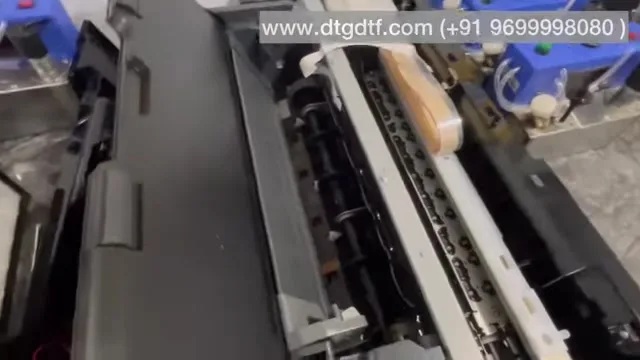
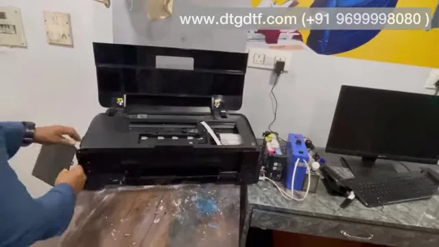
Pickup motor, wheels, roller, rod
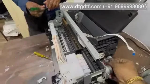
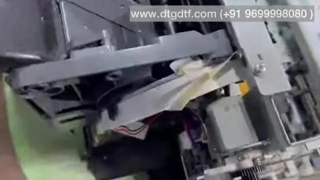
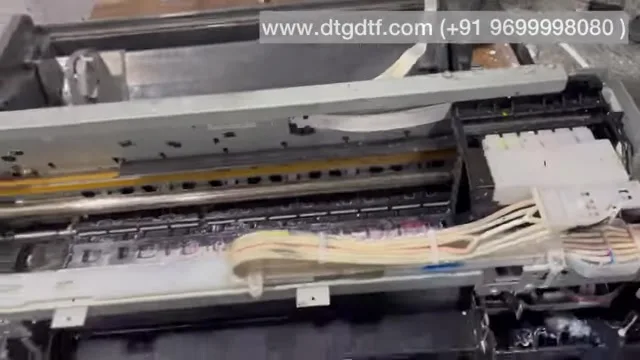
Two screws hold a metal clip on each side; remove both clips. On the right, unplug and unscrew the pickup motor and set it aside; that is the motor we simulate. Press and remove the white wheel and the second wheel. Drag the hook across and pull the roller out; the noise you hear is the clip, nothing is broken. From the other side pull the roller fully; if it sticks, remove the inner pin. Then bend the plastic rod slightly and pull it out one side, then the other. All without removing the chassis, though you can if you prefer.
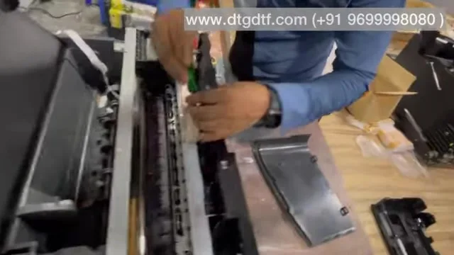
Boards and cables
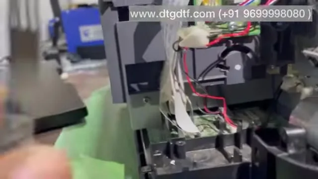
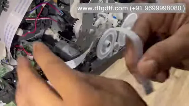
The module is labelled: relay board and main board. Remove the small data cable from the printer's relay and main boards, and the wire that matches the one on the module. Fix the simulator onto the block where the roller mount was, tightly. Connect the main board cable to the main board, lines matching, then the relay board cable to the relay board. One more: a yellow wire on the board comes off. Nothing else is removed; every other pin stays.
Reassemble and test
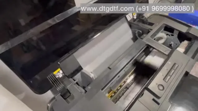
Because the pickup rollers are gone, add a small spring so the remaining rollers sit down rather than springing up. Cover on, switch on: no error. I fed the worst sheet I had, thin and transparent, and it went straight to the rod and printed on AcroRIP 10.3, no stacking, no ejection. The same module prints rolls up to 17 inches. We ship it with most printers and export it to converters abroad.
Today
The L1800 module became the PE/PW bypass module for the L18050 and L8050, with the IVFO beside it; the one-minute version is here, and the complete L18050 conversion is here.
Frequently asked questions
Why does my L1800 keep ejecting DTF film?
Thin, clear film defeats the paper sensor and the pickup roller. The simulator removes the pickup and feeds sheets to the rod.
Do I have to remove the printer chassis?
No. The clips, motor, wheels, roller and rod can be removed in place.
Which cables connect to the simulator?
The main board cable and the relay board cable from the module; the printer's data cable and one matching wire, plus the yellow wire, are removed.
Does it work for rolls?
Yes, up to a 17-inch roll.
Can resellers buy it?
Yes. This video exists for resellers and DIY customers.
More videos: Epson L18050 / L8050 DTF conversion
- Epson L18050 and L8050 Converted to DTF: The Honest, Uncut Review
- Epson L18050 DTF Without Tape: PE/PW Bypass Module, Dampers, Capping and a Live Print
- L18050 Roll Conversion Kit: ASF and PE/PW Bypassed, Forward-Reverse Film Control
- Epson L18050 DTF Conversion, Step by Step: The Complete 38-Minute DIY Guide
- Our Converted L18050 DTF Printer: What We Modify, How You Maintain It, and Who Should Buy It
- Real Facts About the DTF-Modified Epson L805 and L1800: Is This Business for You?